Since I have been unable to track down the source of the interference that occasionally triggers the Blitzortung, I decided on a different approach.
I have noticed with an oscilloscope that when "interference mode" was occurring, it was just barely above the fixed comparator threshold, about 0.5V pk amplitude (1Vp-p). The controller board has a comparator that when the signal amplitude exceeds the threshold, it triggers an ADC read by the micro-controller. By raising the resistance value and making it adjustable, it is possible to raise the trigger threshold above the typical interferences that I have been experiencing.
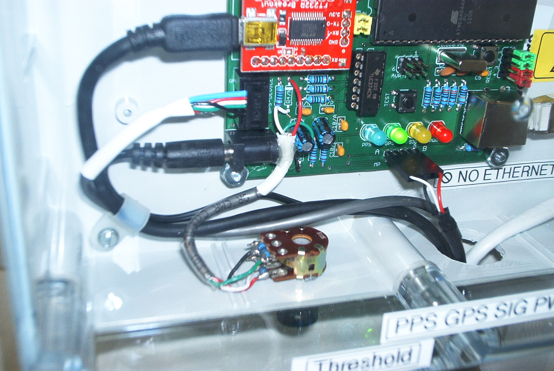
I replaced the two resistors R4/P and R4/N with a 10K dual potentiometer paralleled with 10K resistors. (I know, I could have used 5k pots).
Finding a dual pot that was linear taper was difficult, since most are "audio" taper. For this application you want a linear response.
The window comparator now adjusts from essentially "zero" to just under 1V pk (2Vpk-pk). I can now adjust out an interference mode (steady yellow LED) until it responds normally to lightning events. I have been running with the adjustable window comparator for about two weeks now.
There have been situations where the interfering noise had extremely high amplitude and there wasn't enough range to stop it. Most of the time, though I have been able to eliminate the interference with a turn of the control. (or to be technically correct, stop triggering the ADC read with the higher comparator threshold.)
I'll attach a schematic from a simulation program. Note that the R3 and R4 are actually R4/P and R4/N in the real schematic of the controller board. I ran 4 conductor shielded wire and removed the existing 2k ohm R4/P and R4/N resistors. The wires from the pots went into the holes where the resistors were mounted. I chose to make fully clockwise the maximum voltage window.
When the control is turned counterclockwise, it will always trigger the "interference mode" and always on yellow LED. The control can be adjusted clockwise until the LED just goes out. This does have the effect of reducing the sensitivity to distant strikes, but in "interference mode", nothing gets through anyways.
Here is a picture showing the installed potentiometers and wiring.

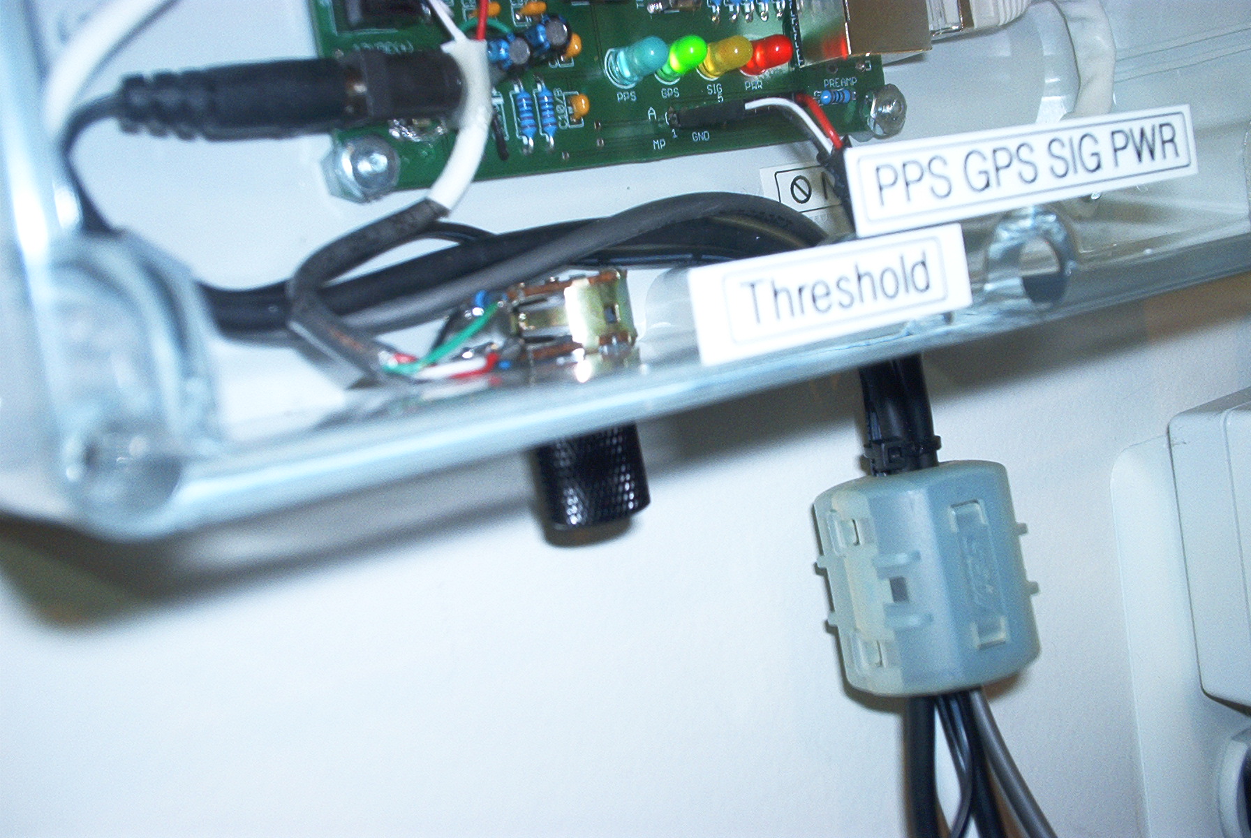
Another shot from the bottom showing the adjustment knob:

Finally the schematic. Again the R3/R4 are incorrect for the real board which have designations R4/P and R4/N.

If anyone is contemplating a Blitzortung build, it might be better to wait for the new "System RED" unit with AGC and remotely adjustable gain.
Greg H