I'm station 1182 in Carlisle MA, USA. When I ordered the kit, there was nobody close, but now there is somebody in the next town over (Westford, MA) (Can you identify yourself?).
My current issue is that the automatic gain/thresholds stuff doesn't appear to work, and finding good values in manual mode is tough. When I think that I have it right, I get a good stroke/signal ratio. Then, without changing anything, the numbers go terrible.
The signals now look pretty clean:
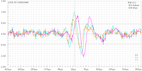
There is some sort of low level noise before the signal and I know that I need to get the antenna into a better position, but I'm not convinced that it is going to help a lot.
I'd like to add the H-field antenna/amplifier so that I can see whether these E-field signals are also H-field (and if so, the direction). Is there any way to get an H-field kit? Or even the board, and I can source the components directly.
Philip
Yeah,,,know what you mean For several days the "Participant's" page appears to have had issues... I suspect that there has been some server work in progress, also, although nothing has been said. I do know that one database wasn't working properly 'till Egon jumped on it. That said, I think it's time for me to fuss a bit... we had a nice page going with station signals and FFT so I'm gonna see what I can do to get that data access back...
Second I do believe you're approaching this correctly, with filters, auto adapt, etc OFF... during this 'quiet time' is a good chance to study your environment... and intermittent noise sources are something we have a lot of fun with... don't worry... it'll change seasonally... and depending on how many orders they have for certain truck axles at the factory over the hill next to me.,...
The "Automatic Mode" has been, and still is, experimental. The actual effect on E field signals is up for debate, since initial 'beta' was for H field. Remembering this is a "hobby" such things are in constant refinement... I personally prefer to remain manual, with no filters, and observe the constantly changing environment.. for the present time my gains on H field are either 10x5 or 8x4... which is way under capability, but new sources have appeared that insist on that reduction. Previously, 10x10 was my 'normal' operation. Now, if I were running "auto" and with those filters, I would be constantly cycling in and out of interference mode... and that is really irritating. So, the 'reduction' in gain dropped me from >1500km to <800Km... so... coincidentally, that is closer to the system 'design parameters'... where the network is actually designed to work most efficiently! (30-500km ±)
Now.. obtaining an H field Red is probably impossible... best to simply wait for next generation... which may knock your socks off,,, if current developer discussion is any indication.
For E field... The channel of most importance is "C"... the wider band.,... If you 'send' anything, always make sure C is sent... you can reduce the gains on the other two to affect the filters for the bands <23kHz and <44kHz... more or less... see
http://www.wxforum.net/index.php?topic=22710.0 which will no doubt add to confusion...

Part of the E field issue may also be due, since you don't run H, to default settings for amp 1... see the clues about "alternate channel mapping"...
You may also be affected by a Navy ELF submarine comm station near your area. You'll have to learn to live with it... or declare war or similar.
Next, remember that a good E field probe is virtually immune to any H field 'M component' signal... so, your 'noise' is almost sure to be 'electrical' ... street light discharge, power line arcing, auto ignition, Navy transmissions with strong signals... plasma TV, arcing dimmers,... somebody running a drill nearby... a kid with a ray gun... Your signals may have a strong 'M" component, but at this discussion, it's more or less irrelevant... you have a strong "E signal"... and an 'H field' amp would almost assuredly show 'junk' unless extremely well shielded. Meantime, enjoy the chase! It's part of the fun! Guys in quiet environments miss all this... you're lucky.
also..... your system (and mine) does not determine if a signal is a "flash"... that's determined on the server... so don't worry so much about sending noise signals... send 'em and let that system in Europe decide what to do with 'em....
Cheers!
Mike


